
Crystal Shortwave Building Instructions
| Home: | Projects: | Crystal Shortwave Radio |
You're eager to start assembly, but a few minutes of preparation will help this project go smoothly. Here's how to get started.
Before you lay hands on any parts, print out this instruction page, the Parts List, and all of the diagrams in the following table.
The large diagrams are designed to print on a standard 8.5 x 11-inch sheet of paper. Most of them are oriented horizontally for easier reading online. Choose your printer's "landscape" mode for the horizontal diagrams, to make sure they'll print on one sheet. Be sure that your printer is set to print at a 1-to-1 ratio, so that the cabinet decal and layout diagram are the correct size.
|
|
|
|
|
|
|
|
|
We recommend getting all of the parts you need before you start assembly. Nothing is more frustrating than getting halfway through a project, then having to wait several days for some missing part to arrive in the mail. The Parts List gives part numbers and sources for all major parts, plus some notes on particular items.
The tools that you'll need are pretty simple—a soldering iron, drill, wire stripper (or knife), screwdriver, and pliers or crescent wrench.
Let's go! The first major step is to drill mounting holes for the controls in the plastic cabinet. The entire radio is mounted to the front panel, making it easy to remove for modifications or simply for showing a friend your handiwork.
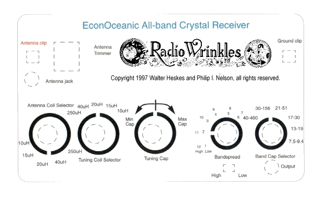
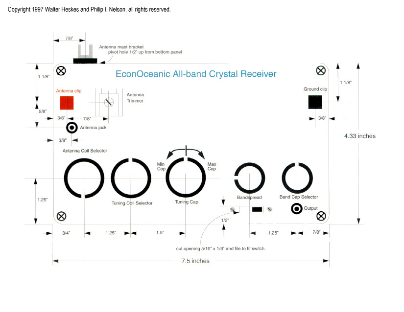
The Component Layout Diagram and Cabinet Decal show you where to drill holes in the cabinet front panel for the components. Carefully trim the decal to fit the cabinet, then punch or cut holes in the decal where indicated. Glue on the decal. Don't put any glue under the places where you'll be drilling holes. Using a scribe or sharp knife, and guided by the scribe marks on the decal, make a little guide hole in the exact center of each place to drill. Using a sharp knife, carefully trim away the paper from each hole, so the drill won't tear the paper.
Regarding the decal, not all printers are created equal, so make sure it's printed at the right size before gluing it on. At the correct size, the decal measures 7.5 inches wide (horizontally) at the trim lines. If you can't get it to print correctly, you can try loading the image into a graphics program such as Photoshop or Paintshop Pro and resizing it for a new printout. The component layout diagram gives exact measurements for the holes, in any case.
Before you drill any holes, check clearances by placing the actual knobs in place atop the diagram. Now drill the holes. Drilling plastic is fast and easy. Wear protective eyegear to guard against flying fragments of plastic.
If you'd like to protect the paper decal against dirt and wear, spray on a thin coat of clear lacquer or poly finish, then set it aside to dry. A more permanent solution would be to have it laminated beforehand at a local copy shop.
Finally, mount the components in the positions shown in the component layout diagram. Pop the front panel into the case and admire your work. From the outside, this project looks almost finished—all that's left is to build the radio that goes inside!
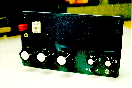
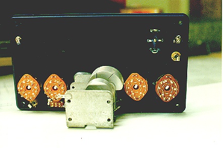
Below are front and rear views of the author's prototype, after mounting the controls on the front panel. (This prototype did not have a decal.)
Switchable coils are a unique feature of the EconOceanic. With many old shortwave radios, changing bands required you to unplug one coil and plug in another. With the EconOceanic, you simply turn switches to change coils in or out. That's more convenient, and it reduces wear and tear on the coils.
In the EconOceanic, all of the BC and SW coils will be wound on a single core. The first step is to get something to wind your coils on. A standard roll of paper towels comes on a 1 5/8-inch diameter cardboard tube, which is just right.
Although you can wind the coils on a single tube, it's a good idea to reinforce the tube with a second stiffening layer, to help resist the tension of the wire as you wind the coils. To create the reinforcement, get an extra cardboard tube, slice it down its length, and remove a 3/8-inch wide strip along the cut, thus reducing its diameter. (Remember that this inner tube has to fit inside another tube of the same original diameter.) Apply a thin layer of Elmer's Glueall to the entire outer surface of the inner tube and insert it through the outer tube. Let it expand and gently press the tubes together to spread the glue. Hold them together for a couple of minutes, then set them aside for the glue to dry. Now you have a single, thick core.
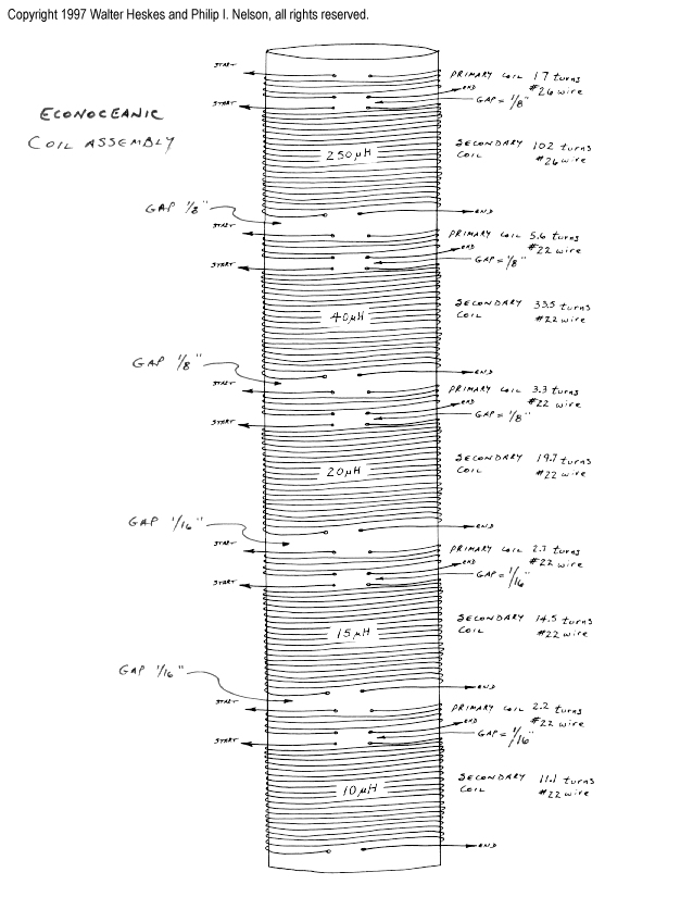
This design requires precise winding, which will be easier if you take a moment to mark your core with lines along its length to indicate its halves, quadrants, and eighth-sections. (In other words, draw eight equally-spaced straight lines, each one going the entire length of the tube.) When you need to wind a coil of 22 3/4 turns, you'll know exactly where to stop during the 23rd turn.
The more accurate your coils, the better they'll work. A coil with the wrong number of turns provides the wrong inductance and will not tune the desired range of frequencies.
It's time to start winding, a task that requires care and precision. Here's a little trick that simplifies the process. As you wind each coil, it helps to apply a thin layer of Elmer's Glueall to hold the most recently wound section together. Otherwise, the wires tend to spring apart (if that happens, you have to rewind the coil from scratch.) Wind about 10 turns, hold them tightly in place with your thumb, apply a pea-sized glob of glue to the wound section, and spread it with the middle finger of your other hand. Work the glue between the coils to encapsulate them. The thin layer dries in a few seconds and you can quickly continue winding. It's a technique you can develop pretty quickly. By the time you've wound all 101.5 turns of the big broadcast (BC) band coil, you'll feel like an expert!
Wind one coil at a time, following the Coil Winding Diagram. Use a full spool of wire when you start winding the big BC coil. It can be heartbreaking to run out of wire just before you reach the end.
Leave 10 inches of extra wire at each end of each coil. It is better to have extra length now which can be trimmed away later. These ends are the leads that you'll connect to the other components. Mark each lead wires using a little flag of masking tape (for instance, "250 uH Antenna" and "250 uH Ground"). The markers will simplify hookup later on.
The chart below lists the number of turns and size of wire to use for each coil. This radio tunes five bands. Each band requires a pair of windings: a small primary and a larger secondary.
| Coil Section |
Number of Turns |
Wire gauge |
| 250uH primary | 17 | 26 |
| 250uH secondary | 102 | 26 |
| 40uH primary | 5.6 | 22 |
| 40uH secondary | 33.5 | 22 |
| 20 uH primary | 3.3 | 22 |
| 20 uH secondary | 19.7 | 22 |
| 15 uH primary | 2.3 | 22 |
| 15 uH secondary | 14.5 | 22 |
| 10 uH primary | 2.2 | 22 |
| 10 uH secondary | 11.1 | 22 |
Each winding must be separated by a small gap from the next. Leave a 1/8-inch gap between windings for the 250uH, 40 uH, and 20 uH coils. Leave a 1/16-inch gap between the 15 uH and 10 uH coils.
Winding can be tedious, but it doesn't pay to rush. If you do this part correctly, you'll have a good-performing radio that performs virtually maintenance-free for many years.
When all the winding is done, check your work to make sure that everything is tight and secure. If necessary, apply more glue where needed. You can also apply a thin coat of clear varnish, if desired, for a more finished appearance.
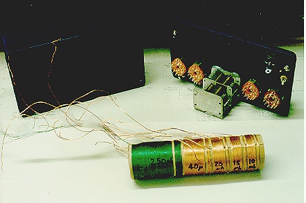
This photo shows the author's prototype coil, ready for mounting.
Mount the coil assembly to the inside surface of the front panel. Check for adequate clearance when the tuning capacitor is fully open. Leave about 1/8-inch minimum clearance between the open rotor and the coil assembly. The rotor and coil must not touch. Mark the center of the coil form and mount self-sticking rubber feet to the centerline of the coil form. The feet serve as standoffs from the front panel, providing some clearance under the coil through which you can pass wires.
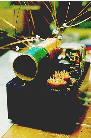
This photo shows the author's prototype coil mounted inside the front panel, which was placed upside down on the cabinet for the photo. Note the little plastic ties used to keep related leads together.
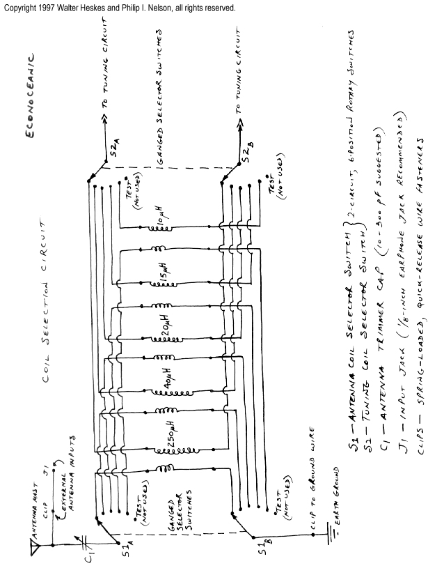
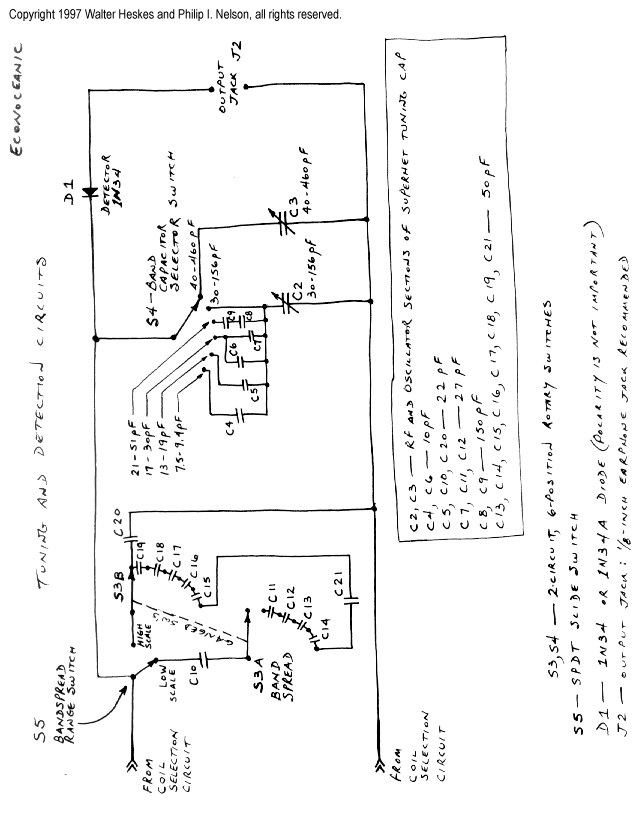
Before you start hooking up components, take a few moments to study the schematic diagrams carefully. The ones you'll be using are the Coil Selector Circuit and Tuner/Detector Circuit.
Let's start by attaching lead wires to the antenna and ground connections. These are shown in the Coil Selector Circuit. Connect wires to both antenna input jacks, the antenna trimmer, and the ground input jack. Check your connections for correctness and solder them.
Identify the pinouts of the rotary switches. Use an ohmmeter to check continuity across the switch circuits and note the position of the switch pointer as each circuit is made. When you are certain you understand how the switch circuits are opened and closed, start wiring the antenna coils to the antenna coil selector switch.
Measure the length of wire needed to span the distance from the coil to the lug at the rotary selector switch. Straight runs are fine. Minimize the number of right angle bends, since those can reduce circuit sensitivity. Trim the coil takeoff leads to approximately 10 inches.
Using a razor blade or fine sandpaper, carefully scrape the enamel coating off each lead wire before you thread it through a lug on the rotary switch. Be careful not to break the fragile lead as you bend it around the lug.
Do not solder any connections until you have checked for proper continuity through each switch circuit and its coil. Refer to the Coil Selector Circuit as needed while checking your work.
After all the antenna coils are wired to the rotary switch, you can begin wiring the tuning coil circuits, referring to the Tuner/Detector Circuit diagram. Again, check for continuity through each switch circuit and its coil. Do not solder until all leads have been properly wired.
Next, connect the leads of the tuning coil to the tuning capacitor.
Connect the ceramic capacitors to the bandspread rotary switch. This is tedious work because the capacitor leads are short and the spacing between adjacent rotary switch lugs is small. Work slowly and carefully.
Connect the leads to the bandspread hi-lo selector switch. Since the DPDT switch has two circuits and only one circuit is needed, you can wire across both circuits if that makes wiring a bit easier for you. Or, use a larger SPDT switch.
Connect the capacitors and leads to the tuning capacitor selector switch.
Connect the leads to the output jack.
You're almost done! Before soldering any connections, follow the schematic diagrams and recheck every connection for continuity. Correct any wiring errors that you find. When you're sure that everything's hooked up correctly, solder each lead.
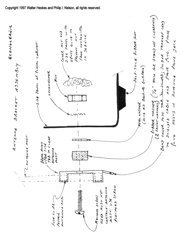
The EconOceanic can use many different kinds of antennas. You'll get the best reception from a long outdoor antenna, of course. In many areas, however, you can get respectable performance from the 6-foot telescoping antenna listed in the Parts List.
To mount the telescoping antenna, modify one of the fuse holder clips as shown in the Antenna Bracket Assembly diagram. The clip forms a swiveling support for the antenna mast. To fasten the antenna mast assembly to the cabinet, you'll also need a small screw, rubber washer, metal washer, lockwasher, and nut.
The moment of truth has arrived! Your new radio should be ready to try out. Go to Using Your Radio.
Copyright 1997 Walter Heskes and Philip I. Nelson, all rights reserved. This radio construction project, including all descriptions, diagrams, photos, and the underlying electronic design, is published here for the noncommercial use of radio hobbyists. You may print and reproduce these project instructions for your personal use. Commercial use of this material is strictly forbidden.