One of the most common areas of confusion in trunked radio scanning is the fleet map. This month we'll take a detailed look at why a fleet map is needed, how they are put together, and a step-by-step plan to figure them out.
There are currently three primary vendors of trunked radio systems of interest to scanner listeners. Motorola is the most popular, followed by GE/Ericsson and E.F. Johnson. GE/Ericsson markets EDACS (Enhanced Digital Access Communications System) and E.F. Johnson sells LTR (Logical Trunked Radio). Each of these systems has been discussed in previous Tracking the Trunks columns.
There are two generations of Motorola trunking systems in operation, Type I and Type II. The more recent Type II systems use a relatively simple method for identifying radios that does not require a fleet map.
Fleet maps are only necessary for Motorola Type I systems.
Transmitting information bitsMobile radios communicate with fixed repeaters by transmitting to the repeater and listening for signals from the repeater. The inbound direction is transmissions from the mobile to the repeater. The outbound direction is transmissions from the repeater to the mobile.
Mobile radios and repeaters exchange information by modulating a radio frequency carrier. The transmitter varies the carrier according to the data to be sent, and the receiver attempts to identify those variations. Because receivers in a typical system are only capable of identifying two different carrier states, the transmitter must deliver information that has been broken down into the smallest size possible.
The smallest unit of information is a binary digit, or bit. A bit has only two possible values, namely either 0 or 1. Put simply, when the transmitter wants to send a 0 it modulates the carrier one way and modulates it the other way to deliver a 1. The receiver identifies the way the carrier is modulated and reproduces the 0 or the 1, as appropriate.
A bit all by itself doesn't carry much information, so bits are usually strung together to form words. The number of possible values a word can have depends on how many bits are in it. A word that has one bit only has two possible values, 0 or 1. A word with two bits has four different possible values, namely 00, 01, 10, or 11. A word with three bits has eight possible values, and so on. See the pattern? Each additional bit doubles the number of possible values. This will become important when we start talking about the capacities of various fleet maps, so bear with me.
| Number of Bits | Possible Values |
| 1 | 2 |
| 2 | 4 |
| 3 | 8 |
| 4 | 16 |
| 5 | 32 |
| 6 | 64 |
| 7 | 128 |
| 8 | 256 |
Outbound Status Word
Because radio signals from mobile units are relatively weak and signals from repeaters are relatively strong, scanner users listen to outbound messages, from the repeater to the mobile.
Motorola repeaters continuously transmit data on the control channel. These data are made up of blocks of information called outbound status words.
The simplest outbound status word (OSW) is made up of 27 information bits divided into three groups. The first 16 bits are used to carry an identification code. The 17th bit is used to signal whether the first sixteen bits refer to a single radio or a group of radios. The remaining 10 bits are the instruction or message the repeater is trying to deliver.
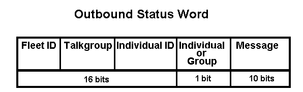
Motorola Type I systems divide up their mobile radios into fleets, subfleets, and individual identities. Since there are a total of 16 identification bits available for use, they must somehow be shared between a fleet identifier, a subfleet identifier, and an individual identifier.
A fleet map is used to figure out how to divide the 16 bits of identification into fleets, subfleets, and individual IDs.
Blocks
Most fleet maps are represented as eight blocks, numbered 0 through 7. Each block is assigned a size code that determines how the identification bits are used within that block. For instance, size code S-5 has 64 fleets, 4 subfleets, and 32 individual IDs. 6 bits are required to represent 64 possible fleets, 2 bits are required to represent 4 possible subfleets, and 5 bits are needed to represent 32 possible individual IDs. This size code uses a total of 13 bits for fleet, subfleet, and individual. The remaining three bits identify the particular block in which this size code resides.
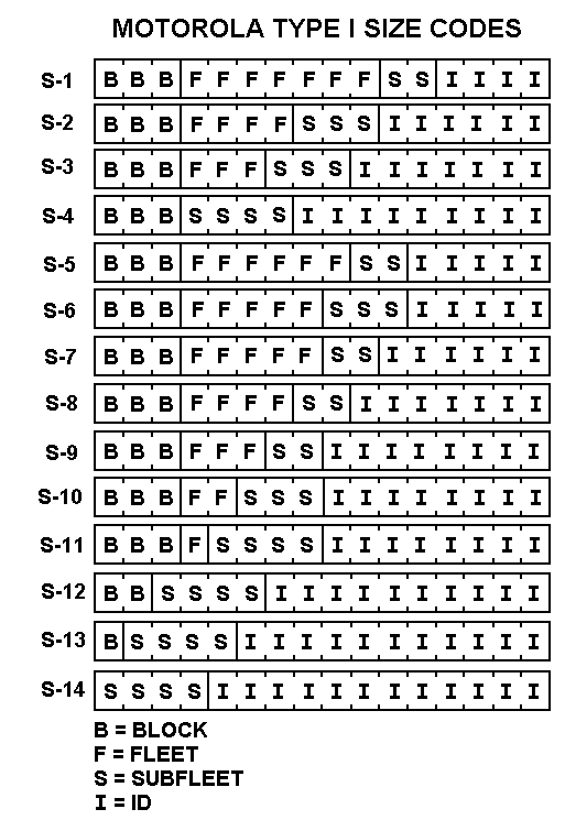
Size codes S-12, S-13, and S-14 are unusual in that they consume more than one block. One or more of the bits usually used to specify the particular block are instead used to increase the number of possible individual IDs.
| Size Code | Fleets | Bits for Fleet | Subfleets | Bits for Subfleets | IDs | Bits for IDs |
| S-0 | Reserved for Type II IDs | |||||
| S-1 | 128 | 7 | 4 | 2 | 16 | 4 |
| S-2 | 16 | 4 | 8 | 3 | 64 | 6 |
| S-3 | 8 | 3 | 8 | 3 | 128 | 7 |
| S-4 | 1 | 0 | 16 | 4 | 512 | 9 |
| S-5 | 64 | 6 | 4 | 2 | 32 | 5 |
| S-6 | 32 | 5 | 8 | 3 | 32 | 5 |
| S-7 | 32 | 5 | 4 | 2 | 64 | 6 |
| S-8 | 16 | 4 | 4 | 2 | 128 | 7 |
| S-9 | 8 | 3 | 4 | 2 | 256 | 8 |
| S-10 | 4 | 2 | 8 | 3 | 256 | 8 |
| S-11 | 2 | 1 | 16 | 4 | 256 | 8 |
| S-12 | 1 | 0 | 16 | 4 | 1024 | 10 (2 blocks) |
| S-13 | 1 | 0 | 16 | 4 | 2048 | 11 (4 blocks) |
| S-14 | 1 | 0 | 16 | 4 | 4096 | 12 (8 blocks) |
Size codes and their corresponding capacities.
Hybrid Systems
Each block in a fleet map is assigned a size code. S-0 is a special code to designate the block will use Type II talkgroups. It is possible have some blocks designated as Type I and others as Type II. These mixed systems are called hybrids, and are usually found in cities that are slowly migrating to new equipment and have a mixture of old and new radios.
Note that Type I and Type II talkgroups will not appear together in the same block.
Determining Fleet Maps
To scan Type I or Hybrid systems, you must program each of the eight blocks with the correct size code. If you pick the right size codes for all eight blocks you will have the complete fleet map and be able to listen to all of the fleet and subfleet combinations used by the system.
Here are some steps you can take to work out fleet maps. I've included some specific instructions for two popular scanners, the Uniden Bearcat BC245XLT Trunk Tracker II and the Radio Shack PRO-92 500-channel Portable Trunking Scanner.
- Be sure all of the radio frequencies for the trunked system
are programmed into the scanner.
Some scanners require that all the frequencies for a particular system be in the same bank of memory. The order of the frequencies is not important for Motorola systems.
- Be sure all talkgroups are unlocked.
On the Bearcat 245XLT this is done by pressing and holding the L/O button until you hear two short beeps, then pressing E. (Page 45 in the Operating Guide).
On the PRO-92 this is done by pressing PGM, then TRUNK, selecting a bank with FUNC or the up/down arrows, then pressing FUNC and 3, then pressing 1. (Page 63 in the Owner's Manual).
- Start by using size code S-0 for each of the eight blocks.
This will allow you to see the full talkgroup ID on the scanner display. Trunk tracking scanners are usually set to scan Type II talkgroups by default. Type II user IDs appear as an even number without a dash (for example, 1440). Type I IDs appear as a 3 or 4 digit number followed by a dash and a 1 or 2 digit number (for example, 160-12).
The BC245XLT defaults to S-0 (Type II), and PRO-92 users should follow the instructions beginning on page 58 of the Owner's Manual.
- Begin scanning the trunk frequencies and write down each of the
different IDs that appear during a conversation.
For the PRO-92 be sure to run in Open Mode (page 64 in the Owner's Manual) so that the scanner will stop on any talkgroup.
- Identify the block in which the talkgroup resides.
You can determine which block an ID belongs to according to the following table:
Block Lowest ID Highest ID 0 0 8191 1 8192 16383 2 16384 24575 3 24576 32767 4 32768 40959 5 40960 49151 6 49152 57343 7 57344 65535 For instance, a talkgroup of 32950 is part of block 4.
- For each of the eight blocks, determine whether it is a Type I or Type II.
If the entire conversation from all parties occurs on the same talkgroup ID, then it's probably a Type II. If the talkgroup changes, or is occasionally an odd number, it's probably a Type I.
If the block is a Type II, leave it as size code S-0 and move on to another talkgroup in a different block.
If the block is a Type I, the next step is to figure out the correct size code.
- Keep track of a conversation and write down all the talkgroup IDs
that appear.
A conversation should only occur between members of the same fleet and subfleet, so the only thing changing is the individual ID. When you've gathered a number of IDs, subtract the lowest numbered ID from the highest numbered ID to get the minimum number of IDs that are part of a talkgroup. Use that number in the following table to figure out the possible size codes.
Size
CodeIDs Bits for
IDsS-1 16 4 S-5 32 5 S-6 32 5 S-2 64 6 S-7 64 6 S-3 128 7 S-8 128 7 S-9 256 8 S-10 256 8 S-11 256 8 S-4 512 9 S-12 1024 10 (2 blocks) S-13 2048 11 (4 blocks) S-14 4096 12 (8 blocks) Size codes ordered according to maximum number of IDs.
For example, if the highest ID is 42151 and the lowest is 42052, the block must support at least 99 individual IDs. Checking the table, size codes S-1, S-5, S-6, S-2, and S-7 are ruled out since they each support fewer than 99 individual IDs.
As a shortcut, the most common number of individual IDs in a fleet/subfleet is either 128, 256, or 512. These correspond to size codes S-3, S-8, S-9, S-10, S-11, and S-4. Note that S-3 and S-8 both allow up to 128 IDs, and S-8, S-9, and S-10 all allow up to 256 IDs.
- Set the proper block to the size code that supports at least the number of individual IDs determined in step 7.
In our example with IDs between 42151 and 42052, we'd set block 5 to size code S-3. For the BC245XLT, set the size code by following the instructions on pages 58 and 59 of the Operating Guide. For the PRO-92, press PGM, then TRUNK, select a bank with FUNC or the up/down arrows, then press FUNC and 8, then follow the directions on the display (pages 58 and following in the Owner's Manual).
- Continue to monitor the talkgroup over time.
If you receive complete conversations, the size code is probably correct. If you occasionally miss part of a conversation, you will probably need to try another size code with the same number of individual IDs (use S-8 instead of S-3, for example) or move to the next higher size code.
Check the Internet
Of course, the easiest way to determine the proper fleet map is to find someone who has already done this work, or who has received the information from a helpful contact at the agency using the system. A number of Internet web sites have such listings of Type I fleet maps, including Uniden's compilation at www.trunktracker.com.
More trunking information is available on my website at www.signalharbor.com, as well as other radio-related information at www.decodesystems.com. E-mail from readers is always welcome at dan@signalharbor.com or dan@decodesystems.com. Until next month, happy monitoring!